Single crank shaft
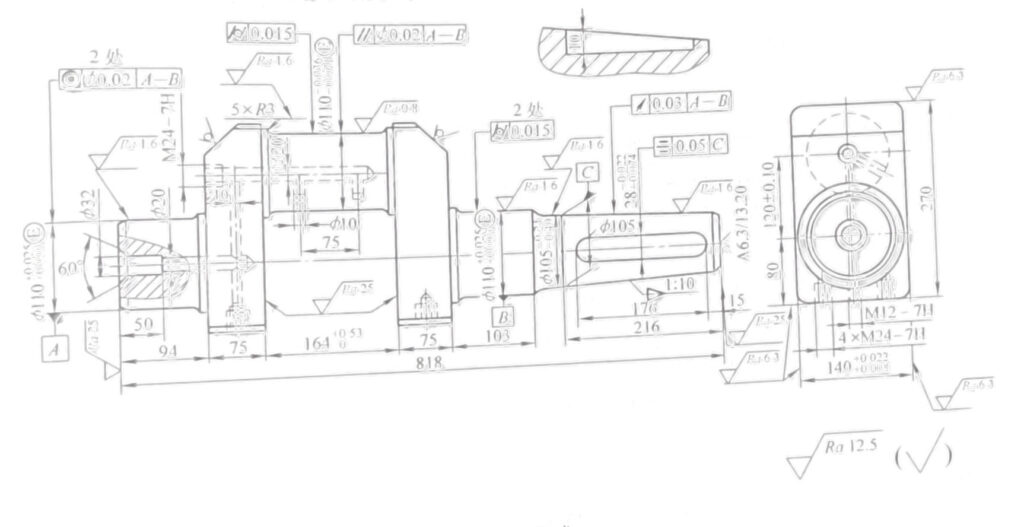
Figure 2-12 shows the structure, dimension and technical requirements of single crank shaft.
1.Part drawing analysis
1) The eccentric distance between crank diameter and shaft diameter of crankshaft is (120 ± 0.10) mm. Pay attention to rotation balance during processing.

Technical requirements
1.The 1:10 conical surface shall be inspected with standard gauge, and the contact surface shall not be less than 80%
2.Remove chips from the oil hole
3.Other chamfer C1
4.Material QT600-3
Figure 2-12 Single crank shaft
2) Keyway 28mm (-0.022, -0.074) × Mm, symmetry tolerance of 0.05mm for 1:10 taper axis.
3) Shaft diameter φ110 (+0.025,+0.003) mm, and turning diameter φ Mm cylindricity tolerance is 0.015mm.
4) Two shaft diameters φ The coaxiality tolerance of 110 (+0.025,+0.003) mm is 0.02 mm.
5) Taper: 1:10, the circular run-out tolerance of axis A – B is 0.03mm.
6) Crank crank diameter φ For axis line 110 (-0.036, -0.071), the parallelism tolerance of axis line A to B is φ 0.02mm.
7) The connection between shaft diameter and crank diameter shall be smooth and rounded. The purpose is to reduce stress concentrations.
8) Taper surface color inspection, its contact surface shall not be less than 80%.
9) All sundries in the oil hole shall be removed after processing.
10) E is the containment requirement.
11) Material QT600-3
2.Machining Process Card of Single Crankshaft (see Table 2-135)
Table 2-135 Machining Process Card of Single Crankshaft
| Process No. | Process name | Process content | Process equipment |
| 1 | Casting | Casting | |
| 2 | cleaning | cleaning | |
| 3 | heat treatment | artificial ageing treatment | |
| 4 | cleaning | Fine sand removal | |
| 5 | paint | Paint red antirust paint instead of machined surface | |
| 6 | Scribe | Align with blank shape, mark main processing line, eccentric distance (120 ± 0.10) mm and shape processing line | |
| 7 | rough mill | Use V-shaped block and lay support to adjust clamping workpiece and then press it tightly (align according to the line), and mill 75mm × 140mm plane (two places) and 270mm upper and lower, with machining allowance of 5-6mm | X62W |
| 8 | milling | In 75mm × 140mm two plane positioning and clamping, alignment according to the line, milling one side, machining allowance of 3mm, thickness of 149mm | X62W |
| 9 | milling | At 75mm × 140mm two plane positioning and clamping, aligning according to the line, milling the other side, leaving a machining allowance of 3mm, ensuring a thickness dimension of 146+85mm | X62W |
| 10 | inspection | Ultrasonic examination | Ultrasonic detector |
| 11 | Scribe | Scribe the center hole lines at both ends of the shaft and take care of the machining allowance of each part | |
| 12 | drill | Place the workpiece flatly on the worktable of the boring machine, press two φ110mm places, and drill the left center hole A6.3 | T68 |
| 13 | rough turning | Clamp the right end (1:10 taper on one side), top the center hole of the left end, and the outer circle of the left end of the car φ 110 (+0.025,+0.003) mm to φ 125 (-0, -0.021) mm (process size), all axle diameters at the right end of the vehicle to φ 114mm ± 0.08mm, rough turning of the left and right end faces on the outer side of the turning diameter, ensuring symmetry and size of 320mm on the outer side of the turning diameter (process size) | CW6180 |
| 14 | rough turning | Left end of clamp (dimensions processed in the previous process) φ 125-0, -0.021), upper center frame at the right end, end face of the car, ensuring a total length of 818mm, drilling center hole A6.3 | CW6180 |
| 15 | milling | At 75mm × 140mm two flat positioning and pressing, in the left end φ 125 (-0, -0.021) mm upper milling keyway width 10mm, depth 5mm, length 80mm (process keyway) | X52K |
| 16 | rough CNC turning | Rough turning radius φ 110 (-0.036, -0.071) mm size to φ 115mm, inner side of coarse turning diameter φ 164+0.53, -0mm to (162 ± 0.1) mm (clamped on the special tool for turning diameter) | CW6180 Special vehicle crank tooling |
| 17 | fine cnc turning | Fine turning radius φ 110 (-0.036, -0.071) mm to 110.8mm ± 0.1mm, on the inner side of the turning diameter of the vehicle φ 164 (+0.53, -0) mm to size requirement, chamfer 3mm | CW6180 Special vehicle crank tooling |
| 18 | fine cnc turning | Clamp right end φ 114mm ± 0.8mm, top left center hole, precision turning axle diameter φ 110 (+0.025,+0.003) mm to φ 111mm, with a length size of 94mm, ensuring a size of 75mm | CW6180 |
| 19 | fine cnc turning | Left end of clamp( φ 111mm), top right center hole, precision turning axle diameter φ 110 (+0.025,+0.003) mm to φ 111mm, with a length dimension up to 103mm, and the remaining parts up to size φ 106mm, guaranteed 75mm size | CW6180 |
| 20 | rough milling | Position with two center holes and grind the right end shaft diameter to φ 110.6 (+0.05,+0) mm, shaft diameter φ 105 (-0.24, -0.40) mm to size φ 105.6 (+0.05,+0) mm | M1450A |
| 21 | rough milling | Position with two central holes, install the clamp upside down, and grind the left end shaft diameter φ 110 (+0.025,+0.003) mm to size φ 110.6 (+0.05,+0) mm | M1450A |
| 22 | milling | Finishing 140 (+0.022,+0.008) left and right sides to drawing size | X62W |
| 23 | milling | First, the bottom surface shall be 75mm x 140mm, positioned and compacted on both sides, and the distance from the center shall be 80mm and the total height shall be 270mm | X62W |
| 24 | drill | With two axis diameters φ 110.6 (+0.05,+0) mm positioning and pressing, drilling and tapping 4 × M24-7H thread | X3050 DRILL DIE |
| 25 | milling | Locate with center holes at both ends and grind the connecting rod diameter φ -0.036, -0.071) mm to drawing size, round corner R3mm | M8260 |
| 26 | milling | Positioning with center holes at both ends, fine grinding of two shaft diameters φ Mm to drawing size, round corner R3mm φ Mm to drawing size, rounded 3mm | M1432 |
| 27 | turning | Left end of clamp, center hole of top right end, turning 1:10 cone, 1.5mm allowance | CW6180 |
| 28 | milling | Locate with center holes at both ends and grind 1:10 cone φ Mm, 216mm long | M1432 1:10 ring gauge |
| 29 | inspection | Magnetic particle testing of each shaft diameter and turning diameter | Flaw detection machine |
| 30 | Scribe | Scribe the keyway line 28 (-0.022, -0.074) mm × Mm | |
| 31 | milling | Milling keyway with two shaft diameters φ 110 (-0.036, -0.071) mm positioning, using specialized fixture clamps, milling key groove 28 (-0.022, -0.074) mm × 176mm × 10mm to drawing size | X52K Special tooling |
| 32 | drill | Left end of drill φ Mm hole, 136mm hole depth, 32mm expansion, 50mm depth, 60 ° angle | T68 |
| 33 | drill | Re-chip workpiece, drill φ Mm oil hole, and M24-7H bottom hole, M12-7H bottom hole, tap M24-7H and M12-7H threads | T68 |
| 34 | drill | Drill 10mm inclined oil hole in the middle of crank diameter, and use special tooling clamp | Z50 |
| 35 | pincers | Repair oil hole, chamfer and remove dirt | |
| 36 | inspect | Check the dimensions of each part | |
| 37 | Warehousing | Oiling and warehousing |
3. Process analysis
1) When aligning and marking with the shape of the blank, consideration should be given to the machining allowance of each part to reduce the scrap rate of the blank
2) When casting the crankshaft, the left end φ 110 (+0.025,+0.003) mm requires a process dimension allowance in the diameter direction, with casting dimensions of φ 130mm, so as to prepare for processing the process keyway before turning. The process keyway is matched with the opening and turning fixture to transmit torque.
3) To ensure machining accuracy, the principle of separating coarse and fine machining should be adopted for all processed parts.
4) The balance device during cutting should be fully considered in crankshaft machining.
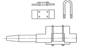
① The special tooling and counterweight device for turning the turning radius are shown in Figure 2-13.
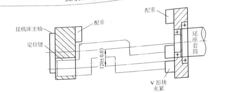
② Coarse and fine turning axle diameters, as well as coarse and fine grinding axle diameters, should be equipped with counterweights on the opposite side of the crankshaft turning diameter, as shown in Figure 2-14.
5) 1:10 taper ring gauge and plug gauge are required to be used together. The ring gauge detects the taper of the crankshaft, and the plug gauge detects the matching motor rotor cone hole or coupling cone hole to ensure fitting accuracy
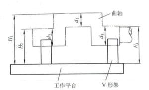
6) The inspection method for crankshaft eccentricity (120 ± 0.1) mm is shown in Figure 2-15. Place the equal height V-shaped block on the working platform to measure the two diameters of the crankshaft φ 110 (+0.025,+0.003) mm as the measurement reference. Place the crankshaft on a V-shaped block, first use a dial gauge to adjust the highest point of the two shaft diameters to an equal height (using paper to pad the V-shaped block), and at the same time use a height gauge to measure the actual dimensions H2 and H3 of the highest point of the shaft diameter (if both shaft diameters are within the tolerance range, H2 and H3 should be at the same height). Use a dial gauge to adjust the crankshaft diameter to the highest point position, and at the same time, use a height gauge to measure the actual size of the highest point of the crankshaft diameter,. Use an outer micrometer to measure the actual dimensions of the turning radius mountain and the shaft light mountain, 4. After calculation, the actual size of the eccentricity can be obtained:

Figure 2-13 Special tooling and counterweight device for turning the crankshaft diameter
Eccentricity=(H1-d1/2)-(H2-d2/2)
In the formula, H1- the highest point of the crankshaft turning diameter;
H2 (H3) – The highest point of the crankshaft diameter;
D1- Actual size of crankshaft diameter;
D2 (d3) – The actual size of the crankshaft diameter.

Fig. 2-14 Shaft Diameter Balance Device for Crankshaft Processing

Figure 2-15 Schematic diagram of crankshaft eccentricity detection
7) Refer to Fig. 2-15 for inspection of parallelism between crankshaft crank diameter axis and axial diameter axis. When adjusting the highest point of the two shaft diameters to the same height with a dial indicator, measure the difference between the two highest points (the distance shall be as far as possible) of the crank diameter d1 with a dial indicator, and then calculate the parallelism value.
8) The crankshaft crank diameter and shaft diameter roundness can be measured with a dial indicator on the machine tool. For cylindricity detection, 2~3 cross sections can be selected on each axis for measurement, and cylindricity value can be obtained through calculation.


