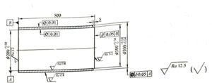
Cylinder liner
Figure 2-20 shows the structure, dimensions, and technical requirements of the cylinder liner.

Technical requirement
1, normalizing 190-207HBW
2. Chamfer C1 is not added
3. Material QT600-3
Figure 2-20 Cylinder liner
1. Parts drawing analysis
- 1) The coaxiality tolerance of the outer circle to the reference A is 0.05mm.
- 2) The parallelism tolerance of the right end facing datum B is 0.05mm.
- 3) The roundness tolerance of the outer surface is 0.01mm.
- 4) The roundness tolerance of the inner circle surface is 0.01mm.
- 5) Normalizing 190~207HBW.
- 6) Material QT600-3.
2. Cylinder liner machining process card (see Table 2-137)
Table 2-137 Cylinder liner machining process card
| Operation number | Operation name | Procedure content | Process equipment |
| 1 | Casting | Cast dimensions φ315mm x φ265mm x 515mm | |
| 2 | Heat Treatment | Manual aging treatment | |
| 3 | Rough turning | Clamp one end of the workpiece outer circle, the inner diameter to the size φ270±1mm, the outer circle to the size φ310mm±1mm, the end face can be flat | CA6140 |
| 4 | Rough turning | Inverted clamping workpiece outer circle, the inner diameter of the other end of the tool to φ270mm±1mm, the outer circle to the size of 310mm±1mm tool, the end face to ensure the total size of 508mm | CA6140 |
| 5 | Heat Treatment | Normalizing 190 to 207HBW | CA6140 |
| 6 | Rough turning ① | Clamp one end of the workpiece outer circle, the inner diameter to the size φ275mm±0.5mm, the outer circle to φ305mm±0.5mm, the end face, to ensure the total length of 506mm | CA6140 |
| 7 | Rough machining | Inverted clamping workpiece outer circle, the inner diameter of the other end of the lathe to φ275mm±0.5mm smooth cutter, the outer circle to the size φ305mm±0.5mm smooth cutter, the end face, to ensure the total length of the workpiece 504mm | CA6140 |
| 8 | Fine machining | Clamp one end of the workpiece to the outer circle (pay attention to reasonable clamping force to prevent workpiece deformation). The inner diameter of the workpiece should be φ279.2mm±0.05mm, the outer circle should be φ300.8mm±0.05mm(pay attention to the length size of more than 250mm), and the end face should ensure the total size of 502mm | CA6140 |
| 9 | Fine machining | Inverted clamping workpiece outer circle, the other end of the inner diameter size to φ279.2mm±0.05mm smooth cutter, the outer circle to the size φ300.8mm±0.05mm smooth cutter, to ensure the total size 500.8mm | CA6140 |
| 10 | Grinding | The workpiece is installed in an outer circle position, and the other end is supported by a center frame. The inner diameter is ground to the drawing size φ280+0.08mm-0mm, and the end face is ground to ensure the total length of the workpiece is 500.4mm | Center frame |
| 11 | Milling | Inverted head, the inner hole positioning clamping workpiece, tail seat with special tooling auxiliary support, grinding the outer circle to the pattern size φ300 (+0.08, +0.04) mm. Loosen the tail seat, grind the end face, ensure the pattern size 500mm, grind the outer circle φ300 (+0.04, +0) mm, the length is 5mm | Professional tooling |
| 12 | Inspection | Check the dimensional accuracy of each part according to the drawing | |
| 13 | Warehousing | Oiling and warehousing |
① When turning the inner diameter and outer circle, the length shall exceed half of the total length.
3.Process analysis
1) The cylinder liner is a thin-walled part. Due to the poor rigidity of thin-walled workpiece, it is easy to deform under the action of cutting force and clamping force during the turning process, which affects the dimensional accuracy and shape accuracy of workpiece. Therefore, reasonable selection of clamping method, tool geometry angle, cutting amount and sufficient cooling and lubrication are the key to ensure the precision of thin-walled workpiece.
2) The accuracy of the inner and outer circles of the parts is required to be high, and the coarse and fine parts shall be separated during processing.
3) When the cylinder liner is finally used, the inner diameter is remachined again after the cylinder liner is pressed into the cylinder block. The end of cylinder liner φ300 (+0.04, +0) mm x 5mm is used for positioning and guiding when it is pressed into the cylinder block.


