2.3.1.3 Connecting rod screws
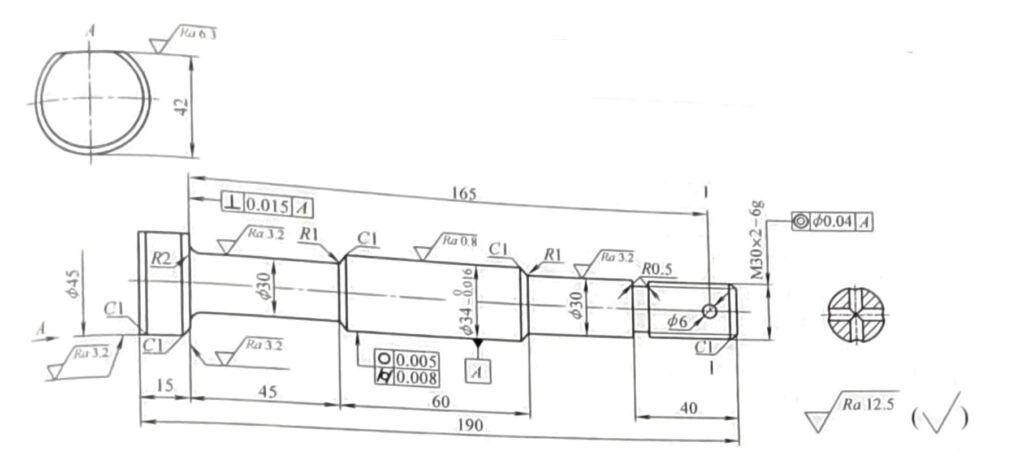
Figures 2-16 show the structure, dimensions, and technical requirements of connecting rod screws.
Technical requirements
1. Tempering treatment 28-32HRC
2. Magnetic particle testing, no cracks, slag inclusions or other defects
3. The roundness and cylindricity tolerance of Φ34 (+0, -0.016) mms 0.008mm
4. Material 40Cr
Figure 2-16 Connecting rod screws
1.Analysis of part drawings
1) The surface roughness value Ra of Connecting rod screw positioning part Φ34 (+0, -0.016) mm is 0.8um, the roundness tolerance is 0.008mm, and the cylindricity tolerance is 0.008mm.
2) Thread M30 × The accuracy of 2 is 6g, and the surface roughness value Ra is 3.2um.
3) Thread head support surface, i.e. close to Φ 30mm rod diameter at one end, right Φ 34 (+0, -0.016) mm axis centerline verticality tolerance. Is 0.015mm.
4) The coaxiality axis tolerance of the Connecting rod screw thread part and positioning reference Φ34 (+0, -0.016) mm is 0.04mm.
5) The connecting rod screw body is subjected to alternating loads, and defects such as cracks and slag inclusions in the material that affect the thread and overall strength are not allowed. Therefore, magnetic particle testing is required for each screw.
6) Tempering treatment 28-32HRC.
7) Connecting rod screw material 40Cr.
2.Mechanical processing process card for connecting rod screws (see Table 2-136)
Table 2-136 Mechanical Processing Process Card for Connecting Rod Screws
| Process number | Process name | Process content | Process equipment |
| 1 | blanking | Bar material Φ60mm × 125mm | saw machine |
| 2 | forge | Free forging forming, forging size: connecting rod screw head Φ 52mm × 27mm, the rod is Φ 41mm ×183mm, with a total length of 210mm (with process allowance) | |
| 3 | heat treatment | Normalizing treatment | |
| 4 | Scribe | Draw the center hole lines at both ends of the blank, taking into account the machining allowance of each part | |
| 5 | drill | Drill center holes A2.5 at both ends | C620 |
| 6 | rough turning | with Φ 52mm × 27mm positioning and clamping (blank size), with the top pressing the center hole on the other end, aligning with the outer circle of the blank, and adjusting the outer circle of the blank Φ 41mm car to Φ 37mm, length 185mm | C620 |
| 7 | rough turning | clamp Φ 37mm outer circle, rough outer circle at the other end of the car Φ 52mm to Φ 48mm | C620 |
| 8 | heat treatment | Tempering treatment 28-32HRC | |
| 9 | fine turning | Repair and grind the two center holes. clamp Φ 48mm (process size), tighten the center hole at the other end, and adjust the outer circle size of the process boss (at the center hole) to Φ 25mm, 7.5mm long, car Φ 37mm outer circle to Φ 35mm, 178.5mm long | C620 |
| 10 | fine turning | Clamp Φ 5mm (padded with copper sheet), turning process boss (center hole part) Φ25mm ×7.5 mm, size 48mm, turning to drawing size 45mm, chamfer C1 | C620 |
| 11 | fine turning | Position with two central holes and clamp with snap rings Φ 45mm outer circle, according to the dimensions of each part of the connecting rod screw in the drawing to meet the requirements, where Φ Leave a grinding allowance of 0.5mm at Φ34 (+0, -0.016)mm to ensure the head of the connecting rod screw Φ 45mm long, 15.1mm long, with a total length of 190m, and a portion of the thread growing out of one end Φ 25mm, from the screw position part to Φ 30 (+0.25,+0.15) mm | C620 |
| 12 | fine turning | clamp Φ 34mm outer circle (padded with copper sheet), and align the outer circle, with M30-6g car level and chamfer C1 | C620, Ring gauge |
| 13 | grinding | Positioning and clamping with two central holes, grinding Φ 34,5mm size to the drawing requirement of Φ34 (+0, -0.016)mm, while grinding Φ 45mm right end face, guaranteed size 15mm | Grinding machine, M1420 |
| 14 | milling | Use a V-shaped block or combination fixture to clamp the workpiece, and mill the center hole process boss at one end of the thread to be flush with the thread end face. Be careful not to damage the threaded part | X62W, dedicated tooling or combination fixture |
| 15 | milling | Use V-shaped blocks or combination fixtures to clamp the workpiece, mill the other end of the process boss, and The Φ45mm end face should be flush, and be careful not to damage the chamfered parts | X62W, dedicated tooling or combination fixture |
| 16 | milling | Use V-shaped blocks or combination fixtures to clamp the workpiece and mill it Φ 45mm at the 42mm size to (42 ± 0.1) mm, which is used in the following processes | X62W, dedicated tooling or combination fixture |
| 17 | drill | Use a dedicated drilling jig or combination fixture to clamp the workpiece and drill 2 ×Φ 6mm hole [positioned with a size of (42 ± 0,1) mm] | Z512 |
| 18 | inspection | Inspect each part according to the drawing requirements and conduct magnetic particle testing | Special inspection tools and testing machines |
| 19 | Warehousing | Apply anti rust oil, package and store in storage |
3. Process analysis
1) Connecting rod screws are very important components in the entire connecting rod assembly, as they withstand alternating loads and are prone to fatigue fracture. Therefore, they themselves need to have high strength. In terms of structure, each variable diameter area is transitioned with rounded corners to reduce stress concentration. Positioning dimensions Φ 34 (+0, -0.016) mm, both sides are in the middle Φ The 30mm size is mainly for assembly convenience. stay Φ The 45mm cylindrical head part is milled flat (size 42mm) to prevent rotation when tightening the screws.
2) The raw material is a 40Cr forging, and according to the different processing quantities, free forging or die forging can be used. After forging, normalizing is required. The purpose of forging is to improve the properties of materials.
The cutting size is Φ 60mm × 125mm is used to ensure a certain forging ratio to prevent metal burning and ensure sufficient raw material usage.
3) The quenching and tempering treatment required by the drawing should be arranged after rough machining. In order to ensure the machining allowance after quenching and tempering deformation, a 3mm machining allowance should be left during rough machining.
4) It is not allowed to leave a central hole on the connecting rod screw, and during forging, a process allowance is left on both sides Φ 25mm × 7.5m
Process boss, the center hole is drilled on the boss, and the center hole is A2.5.
5) M30 × For the processing of 2-6g threads, it is not advisable to use the method of flat tooth sleeve threads (as this method cannot meet the accuracy requirements). Instead, thread turning tools should be used to turn the threads.
6) During heat treatment, attention should be paid to the stacking of connecting rod screws and it is not allowed to place them alternately to reduce the deformation of connecting rod screws.
7) To ensure the support surface of the connecting rod screw head (i.e. close to Φ The perpendicularity requirement for the axis of the connecting rod screw with a diameter of 30mm at one end during grinding Φ When the outer circle is 34 (+0, -0.016) mm, it is necessary to use the method of grinding wheel against the end face to machine the supporting surface. Before grinding, the grinding wheel should be trimmed to ensure the rounded corners and perpendicularity of the grinding wheel.
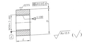
8) To the supporting surface of the connecting rod screw head (i.e. close to the inspection of the perpendicularity of the centerline with a diameter of Φ 30mm at one end can be carried out using a dedicated inspection tool in conjunction with the coloring method, as shown in Figure 2-17. Special inspection tools and connecting rod screws The matching aperture of Φ34 (+0, -0.016) mm should be segmented according to the actual tolerance of the workpiece. During the inspection, the supporting surface of the connecting rod screw is painted and compared with the end face of the special tool. When the contact surface between the supporting surface of the connecting rod screw head and the end face of the inspection tool is more than 90%, it is considered qualified.

Technical requirements
1.The Φ34mm size is divided into three size segments, Φ34 (+0.013, +0.005)mm,Φ34 (+0.005, -0.010) mm, and Φ34 (+0.010, -0.025) mm
2. Heat treatment 56-62HRC
3. Material GCr15
Figure 2-17 Verticality Inspection Tool for Connecting Rod Screws
9) Connecting rod screw M30 × The coaxiality inspection of the 2-6g threaded part with a positioning diameter of Φ34 (+0.010, -0.025) mm can be carried out using a special inspection tool (see Figure 2-18) and a standard V-shaped block.

Technical requirements
1. Tempering treatment 28-32HRC
2. Material 40Cm
Figure 2-18 Connecting Rod Screw Coaxiality Inspection Tool
The characteristic of the special inspection tool is the use of a 1:100 taper thread sleeve. The coaxiality tolerance between the outer diameter of the threaded sleeve and the centerline of the internal thread is required to be within 1/2 of the coaxiality error of the part to eliminate errors in pitch diameter machining.
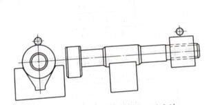
The inspection method is to first screw the connecting rod screw and the taper thread sleeve together, use Φ34 (+0.010, -0.025) mm in the connecting rod screw as the positioning reference, place it on a V-shaped block (V-shaped block is placed on a standard flat plate), and then rotate the connecting rod screw. At the same time, use a dial gauge to detect the runout of the outer diameter of the taper thread sleeve, and the dial gauge reading is the error value (see Figure 2-19).

Figure 2-19 Inspection method for coaxiality of connecting rod screws


