2.2.4. Structure between modules of a multi microprocessor CNC device
The interconnection and communication between various modules of a multiprocessor CNC device mainly adopts two types of structures: shared bus and shared memory. See Table 2-7 for details.
Table 2-7 Structure between modules of multiple microprocessors
| Number | Structure between modules | Detailed description |
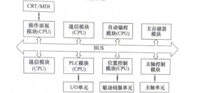
| 1 | Shared bus architecture | The shared bus structure is shown in Figure 23. The bus connects various modules together, transmits signals as required, and achieves predetermined functions. The shared bus structure system is flexible in configuration, simple in structure, and easy to implement. Its disadvantage is that when each main module uses the bus, it will cause “competition”, which reduces the efficiency of information transmission. Once the bus fails, it will affect the overall situation. However, due to its advantages of simple structure, flexible system configuration, easy implementation, and low cost of passive bus, it is often used.
Figure 2-3 Hardware Structure of CNC System with Shared Bus Structure |
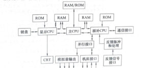
| 2 | Shared memory structure | The structure of shared memory is shown in Figure 2-4. Multi terminal ☐ memory is used to achieve interconnection and communication between microprocessors. Each terminal ☐ is equipped with a set of data, address, and control lines for use and access by the terminal ☐. Due to the complex design of multi terminal ☐ memory, and for more than two main modules, there may be congestion in memory transmission due to contention for memory. Therefore, this structure generally uses dual terminal ☐ memory (dual port RAM)
|


